FAQs
Here we list frequently asked questions when diving deep into TransducerM usages.
Background knowledge of the TransducerM User Guide maybe required to understand the content.
Q: How can the data rate output by IMU assistant be improved? And how to ensure high sampling rate of data in multi data output mode?
A:
For models TM131 / TM151 / TM171 / TM210 / TM210-G / TM310 / TM362 / TM510 :
(1) Set the Output Data Rate (ODR) to the desired value. The maximum ODR is according to the product datasheet. The typical maximum values are 200Hz, 400Hz and 800Hz (800Hz is for certain models only, such as TM171, TM210, and TM362 and TM310 ordered since January 2025).
(2) Set a proper buffer size in the host computer to make sure all data sent from the TransducerM are timely parsed:
1) Implement the trick described in User Guide section "Avoid Buffer Overflow" (For User Guide Version 1-3-5-R1, it is on page 28)
2) If the method (1) does not fully help, adjust the buffer size in the communication library in a file named "Easyprofile/BasicTypes.h":
Adjust the EP_BUFFFER_MULTIPLIER_ definition to a larger value (such as 10)
(3) Match baudrate with ODR. When 400Hz or 800Hz are selected, it is required to use 230400 bps, 460800 bps or more bit rate for UART depending on the number of different data types selected for output, or 0.5Mbps or 1Mbps for CAN Bus (for TM310, TM362 and TM510 with CAN Bus interface). The alternative USB interface (TM151, TM171, TM210, TM210-G and TM362) uses baudrate according to USB2.0 and does not require manual setup.
For legacy TM200 / TM35x models:
(1) Set the inhibit time to 0 (zero) and communication rate to 1Mbps (4Mbps is not necessary and we don't recommend that) will increase the output to its maximum (close to 300Hz, meaning 300 complete data package per second)
(2) Set a proper buffer size in the host computer to make sure all data sent from the TransducerM are timely parsed:
1) Implement the trick described in User Guide section "Avoid Buffer Overflow" (For User Guide Version 1-3-1-R3, it is on page 27)
2) If the method (1) does not fully help, adjust the buffer size in the communication library in a file named "Easyprofile/BasicTypes.h":
Adjust the EP_BUFFFER_MULTIPLIER_ definition to a larger value (such as 10)
(3) Only select the most needed data package. For example:
1) When output data type RawData, Status, Quaternion and Gravity are all selected, you get around 75Hz update rate for each of the output data type (75Hz * 4 = 300 Hz) if the above (1) and (2) are properly implemented;
2) If you uncheck the Status and Gravity data type, and only output RawData and Quaternion, you get around 150 Hz update rate for each of the output (150Hz * 2 = 300 Hz).
This is due to the fact that the data package shares the bandwidth of the serial port output capacity.
For TM35x / TM500:
Q: What is the bias repeatability / error of TransducerM in typical user scenarios?
A: (1) For TransducerM TM500-61 series:
The Turn-on to turn-on bias (Bias Repeatability) of the gyroscope installed: typical bias is 0.03 deg/sec, maximum 0.15 deg/sec, under constant environmental temperature. The bias deviation over temperature: typically 0.002 deg/(sec*Celsius) , maximum 0.004 deg/(sec*Celsius). Combing the above error in possible worst case scenario (turn on at -40 Celsius, and then turn on at +85 Celsius) :
Bias error (typical) = (40+85)*0.002 + 0.03 = 0.28 deg/sec
Bias error (max*) = (40+85)*0.004 + 0.15 = 0.65 deg/sec
*The actual max error may be influenced also by other error affects.
(3) For TransducerM TM500-75 series:
When properly powered on, and TransducerM reports QoS reaches 5, typical city car driving test shows less than 1.5 degree per 30 minutes pure inertial error in heading angle.
(3) For TransducerM TM35x series:
When properly powered on, and TransducerM reports QoS reaches 5, typical city car driving test shows less than 10 degree per 30 minutes pure inertial error in heading angle.
(4) Important notes:
Besides the bias repeatability from gyroscope specs alone, the TransducerM also has sophisticated dynamic compensation algorithm running inside. The compositive bias repeatability may be better in an actual user case. For example, on ground vehicle scenario, the TM353 shows similar bias turn-on repeatability to TM500-61 since we can take the advantage of calibrating during vehicle idling. There are APIs to help further reduce error by interfacing the TransducerM to the on-board computer of the vehicle.
For TM35x:
Q: How often should the Run-time Static Calibration (Forced Calibration) be performed?
A: The "Run-time Static Calibration (Forced Calibration)" is regularly needed for the drift compensation, even at seemingly constant ambient environment, due to the fact that the thermal condition in the vicinity of the TransducerM may still be changing; in addition, there is also error caused by the “random walk” effects of the sensor.
Our recommendation: To achieve adequate precision, if possible, perform Full or Partial Calibration (see definition below) as often as possible such as every few minutes (e.g. 5 minutes, or 1 minute, 7 minutes, etc.) when the robot/vehicle gets a chance to stop by. Make sure that within around every half hour, there is at least a Full Calibration. If not possible to perform at such frequency, then at least one full calibration around every half hour. It is not recommended to perform the calibration at a frequency lower than one full calibration per an hour.
Full Calibration and Partial Calibration: A “Full Calibration” as mentioned above means the time interval between the calibration start command and stop command (calibration time) is at least 12 seconds. If the calibration time is less than 12 seconds, it is a “Partial Calibration”, under which circumstance the data collected during calibration will be used for compensation but with less confidence, since less data means random jitters cannot be removed fully and therefore less trustworthy. Therefore, after Partial Calibration there exists some residual error. The Partial Calibration uses less time (any time period between 0 seconds to 12 seconds) and changes the error prediction matrix gradually inside the TransducerM while a calibration time over 12 seconds forces the TransducerM to replace the old error prediction fully using new prediction, which results in a “Full Calibration” .
If the error is too large then (1) try to increase the frequency of Full Calibration, (2) try to make sure the robot/vehicle is not moving during the calibration (note that the vibration caused by such as cooling fans, etc., will not affect the accuracy of calibration).
All TransducerM series:
Q: How to compile the C/C++ communication library?
A: The C/C++ libraries we provide together with the product, is platform independent, which consists of the “EasyProfile” folder which is the library itself, and an example main.c / .cpp file which is written in pseudo-code or real-code targeting a specific platform. Generally speaking, if you follow the following steps, it will compile properly to your target platform (for example, PC platforms, Linux/POSIX systems, Linux systems with ROS framework, embedded systems with or without OS, etc.)
(1) Firstly, you may need a working “Hello-world” program written in C/C++ language for your target platform that can do basic reading and writing to the serial port. Such example program varies from platform to platform and can usually be found in your target platform learning material.
(2) Copy the entire EasyProfile folder into your "Hello-world" project folder.
(3) Adjust your serial port read and write routine according to the example main.c / .cpp from the library.
(4) Generate a makefile. If you are writing the code in bare text editor, such as VI / Emacs / Nano Editor, you may need to manually write the makefile; if you are using some IDE, the IDE may help you generate proper makefile once you have completed the import of the library files.
(5) Make and build the project. If your compiler complains about some error, then slightly modify the library code according to the error message. This is not uncommon to have some errors at first compile since different C/C++ compiler has slight variations on its sensitive level to warning and error generation routine.
You will need to compile all .h .c/.cpp source code files inside EasyProfile folder. However, the main_example.c cannot be compiled directly (and also there is no need to compile main_example.c, as this file is only served for demonstration purpose on how you can integrate the library files to your own project.
Below are some additional information: The main_example.c is written in a mixture of C and human language, since we do not know how exactly the serial read and write functions look like in your platform, and you will need to adjust it by yourself.
For example, inside the main_example.c, there is a line looks like: SerialPort_SendData(txData, txSize)); This line is what we call the “pseudo-code”, since it cannot be compiled as there is no such function called “SerialPort_SendData” ever defined. There may be some function in your platform called serail_write(), or any other name, that does the same job, then you will need to replace the SerialPort_SendData by the function name that actually does the job. After you have replaced all the pseudo-code, the migration is complete, and the results can be compiled properly to call the communication library inside the EasyProfile folder.
Q: I have forgotten which baudrate was set to the TransducerM, now IMU Assistant is unable to communicate with the TransducerM, what should I do?
For models TM151 / TM171 / TM210 / TM210-G / TM362:
A: Simply uses its USB interface to connect and find or reset the baudrate.
For models TM200 / TM35x :
A: The TransducerM TM200 / TM35x has a mechanism to help find its current serial port baudrate setting. The principle behind, is that the TransducerM will always use default 115200 bps to communicate through serial port during the first 6 seconds after power on, if, during this period, an IMU Assistant “SCAN” request is received from the host PC, the TransducerM will lock its serial port baudrate to 115200 bps for the current session, instead of switching to user baudrate setting after 6 seconds. This allows to communication with IMU Assistant even if the TransducerM user baudrate setting is known.
Step by step operation guide:
1. Open the USB-to-Serial adapter COM port in IMU Assistant
2. Disconnect TransducerM with the USB-to-Serial adapter (while keeping the USB side connected to PC and with the port open in IMU Assistant)
4. Click SCAN button in IMU Assistant
5. Connect TransducerM to the USB-to-Serial adapter while SCAN is running (this will automatically trigger TransducerM to use default 115200 bps baudrate)
6. The TransducerM node should then appear in IMU Assistant; check its baudrate setting, and if too high, lower it down or switch to default 115200 bps, or set IMU Assistant to match the TransducerM baudrate setting before next connection.
If the above does not help, try:
swap the RX TX wire, and repeat the above process.
If the above does not help, further try:
Check if it is the right COM port opened by the IMU Assistant
If the above does not help, further try:
To resolve issues caused by low voltage (applicable only to TransducerM TM500)
1. If the cable is too long, the resistance in the cable lowers the voltage and if the voltage at TransducerM is below 9V (in some models, 5V) then it causes boot problems, consequently the module will not be recognized by IMU Assistant.
2. Try to adjust the input voltage to a higher value such as 12 volt (again, this only apply to TM500! TransducerM TM35x does not support higher voltage than 5.5V).
For models TM310 and TM510:
A: Forgetting its baudrate is unacceptable. Please try different baudrate by pressing and hold the button of the dedicated USB2CAN adapter until it flashes both of its LEDs, and find the correct one. For improved reliability, these models does not have complex baudrate recovery mechanism or exposed USB interfaces.
Q: Why does TransducerM always maintain QoS 2?
For TM200:
A: 1) If the TransducerM TM200 runs firmware version V25.4.5 or later, some of the run-time gyro error prediction algorithm is automatically turned off when the AccGain Configuration is set to higher than 2.99 (refer to the screenshot below).
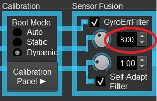
Such configuration is designed for using TransducerM in surface vessels -- It helps to avoid the false estimation of bias error caused by slow motion of the vessel.
2) Check whether TransducerM is moving constantly
For example, when TransducerM is installed on a boat and the boat is floating on water, where the wave causes the TransducerM to move all the time with the boat. Another example is that if there is motor vibration noise in the vicinity. Under such circumstances the TransducerM has relatively low confidence on the estimated gyro bias error, causing QoS to staying at 2.
3) If you leave the TransducerM in a static environment (no motion, no vibration, no finger taps on the table if the TransducerM is placed on the table) with AccGain<2.9 for over 2 minutes, and the QoS still does not raise to 3 or higher, then you may need to perform a New Install Calibration (User Guide section keyword “Calibration Panel” and "CalibB", the section is typically near page 15 of the TM200 User Guide). Please make sure the power supply is stable during and at least 30 seconds after successful calibration to allow correct calibration data saving to the flash memory.
The TransducerM still functions well in QoS 2, which only indicates that due to the environment, the error prediction is not perfect, and therefore compromises its dynamic and staic accuracy. In most cases, to increase QoS, it simply requires to place the TransducerM in a static condition. The TransducerM also estimate the error realtime in motion, however, the convergence is not as good or as fast as when in static environment, especially in terms of bias error prediction.
Q: How to eliminate the accumulated error of Yaw ?
A: When relying on TransducerM without external correction signal, there will be accumulated error on heading over time. Common practices to remove the error can be either of the following:
1. If the installation surroundings and the operation environment is clean from magnetic field interference, we can use the magnetometer measurement to correct the heading. We have demo code to extract digital compass heading from TransducerM. If you would like to have the code, please let us know.
2. If the mobile robot is equipped with other navigation sensors, such as GPS, laser range finder, wireless beacon positioning sensor, visual sensor, etc., they can help to remove the long-term error on heading. While TransducerM provides relatively more accurate and real-time reading on heading within a short period, the other sensors provide intermittent corrections. For example, a laser range finder, together with SLAM algorithm, can be used to derive robot heading, although it is in low refresh rate, and much noisier than TransducerM output, it is statistically correct over time. We can use that statistics to correct TransducerM heading. The same principle applies when the robot is equipped with other sensors such as a GPS, a visual sensor, etc. If you need assistance on how to correct TransducerM heading using noisy heading output from other sensors, we will be glad to assist.
About the calibration interface of TransducerM TM300 series:
If the TransducerM drifts <8 degrees (or <4 degrees for TM362) on heading per hour, it is already a result that we considered as normal performance under certain working conditions; therefore, we do not think it is necessary to perform the “New Install Calibration”. The “Run-time Static Calibration (Forced Calibration)” helps to slow down the error accumulation on heading, but it does not remove the already accumulated heading error (since TransducerM is an inertial device and all it does about heading is, in principle, by dead reckoning). We still recommend to always use the “Run-time Static Calibration" if the robot/vehicle operation condition permits this calibration to be performed correctly, since it slows down the error accumulation especially in a long mission lasts several hours or more. To remove the heading error in indefinite long period, normally we will need the assistants from other references.
Q: You claim to have incredible position tracking accuracy -- How is it done (double integration or wheel odometry)? and what's the assumed accuracy of the wheel odometry ?
A: When doing wheel odometry (i.e. TransducerM outputs Quaternion, and on the robot / vehicle there should be an odometer and onboard computer combing the Quaternion and odometer reading), and with a properly warmed up TransducerM and typical factory autonomous vehicle driving routs planning, the position tracking accuracy can reach some 0.2% of the distance traveled. The result is achieved with an wheel encoder not by integrating its accelerometer data (double integration).
Q: ROS support - do you formally support ROS ?
A: We have simple ROS example code in C++ language which is available at Download Center for demonstrating how to read sensor data in ROS environment as a node and user may further enhance it or modify it for their own purpose. However, generally speaking, the TransducerM sensor itself is independent from any platform, in addition we provide C and C++ communication library in source code, which usually complies well with little modification needed to fit a target system - whether it is a PC, an embedded Linux system, or a simple microcontroller without OS.
Q: Calibration on Linux - is it possible or only in Windows ?
A: The TransducerM module is factory calibrated with primary calibration data stored in its Flash memory which is not modifiable. In addition, we provide a calibration interface for removing gyro drifting (zeroing of bias). The interface can be accessed by sending commands to the module, and as such it can be performed by any PC or micro-controller with its interfacing port (such as serial port/CAN Bus/USB where applicable denpending on different TransducerM models); the command table is available in the product User Guide. If you are using Windows, you take advantage of our graphic user interface ImuAssistant so that such operation can be performed by simple clicking of a few buttons. The graphic user interface ImuAssistant is just like a command terminal -- it sends commands and displays data results but does not do any actual calculation work; in other words, the process is done by TransducerM itself, that is why all operations can be performed even without the ImuAssitant GUI or Windows OS.
Q: The Yaw drift is worse than roll and pitch - for 2D applications how come this is so given the integrated magnetometer ?
A: The magnetic field is easily interfered by the surroundings, that is why the TransducerM products embeds carefully designed filter to remove the disturbances, however, such filter has a side effect that it causes accumulated error in heading angle – this is not difficult to understand: in distorted magnetic field one cannot tell the Earth magnetic north, the filter can try to stop the heading (Yaw) from drifting caused by the gyroscope using the then-current field, but it will not have the chance to figure out which portion of the field is actually the magnetic field generated by the Earth.
As a result, the heading (Yaw) drift is inevitable, while roll and pitch angle can be compensated constantly by the gravity, hence smaller error (and also no accumulated error) in roll and pitch.
If the magnetic field is good, the heading can be maintained using magnetometer and digital compass function (available with TransducerM with digital compass feature, such as TM171, TM210, TM310, TM362, TM500, TM510).
Q: For robot vehicle on rough floor, the precise roll and pitch are critical to transform the data given by LIDAR and cameras. This requires the IMU to act as a time-accurate inclinometer. Do you support external PC clock sync like NTP ?
A: The module does not support NTP, however it outputs timestamp in micro-seconds with each data package. With around 1Mbps serial data rate plus Inhibit Time set to 0 or ODR (Output Data Rate) set to equal to or higher than 100Hz, TransducerM output data rate can easily reach 100 Hz or above. Some TransducerM (including but not limited to TransducerM TM171, TM362) can reach 800Hz output maximum.
For an uneven ground, it is important to have accurate real-time roll and pitch reading (or Quaternion), and TransducerM should be among one the best in its price range to do the job in terms of it having very good stability in roll and pitch when subjecting to vehicle acceleration and deceleration. According to our experience, the resistance of the TransducerM sensor module to roll and pitch error caused by external acceleration and vibrations plays a more important role in overall error reduction than having an absolutely correct timing. The timing error is systemic and can be compensated. You may compare different products for their accuracy in roll, pitch and yaw output simply by installing them together in your passenger car and drive around in street or off-road, accelerating and decelerating, if you follow the TransducerM test procedure in the User Guide (refer to User Guide section "Standard Setup and Test Procedure" or similar titles), you may find it outputs well along with other interesting results.
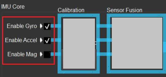
Q: Enable Checkboxes
A: In the ImuAssistant configuration panel, if “Enable Gyro”, “Enable Accel” and “Enable Mag” are all checked (enabled), then the Quaternion is the result of sensor fusion of all the 3-axis gyroscopes, 3-axis accelerometers and 3-axis magnetometers.
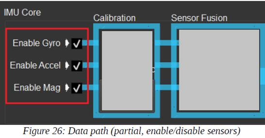
Similarly, if only “Enable Gyro” and “Enable Accel” are checked, then the Quaternion is the result of sensor fusion of the 3-axis gyroscopes and 3-axis accelerometers (meaning without 3-axis magnetometers).
You may also“Enable Gyro”only, which will result in the sensor fusion only using the 3-axis gyroscopes, and since there is no correction from accelerometers or magnetometers, the results will drift gradually.
Note 1: When the “Self-Adapt Filter” and “Enable Mag” are checked, the effects from the correction of magnetometer is not instantly obvious, but it does have differences especially in Yaw stability compared to the configuration without“Enable Mag”checked.

Note 2: The Euler, RPY and Gravity output is calculated (derived) from the Quaternion and therefore follow the above rules as well.
Note 3: “Enable Gyro”, “Enable Accel” and “Enable Mag” checkboxes do not affect Raw Accelerometer, Gyroscope and Magnetometer output.
---
If you find any error on the page please contact us.